Showing posts with label Acura. Show all posts
Showing posts with label Acura. Show all posts
Acura NSX Variable Valve Timing Lift Electronic Control VTEC Parts Diagram
The 1991 Acura NSX engine features Variable Valve Timing and Lift Electronic Control (VTEC) System. The engine is equipped with multiple cam lobes per cylinder, providing one valve timing and lift profile at low speed and a different profile at high speed. Switch-over from one profile to other is controlled electronically, and is selected by monitoring current engine speed and load. The following schematic shows Acura NSX Variable Valve Timing Lift Electronic Control VTEC Parts Diagram and Components.
LEGEND:
1 – Cam lobes for low rpm
2 – Cam lobes for high rpm
3 – Primary rocker arm
4 – Mid rocker arm
5 – Secondary rocker arm
6 – Lost motion assembly
7 – Intake valve
8 – Exhaust valve
lifters and engine diagram,engine valve diagram,acura nsx Variable Valve Timing,engine valve timing,Variable Valve Timing Diagram,
ReadMore..
LEGEND:
1 – Cam lobes for low rpm
2 – Cam lobes for high rpm
3 – Primary rocker arm
4 – Mid rocker arm
5 – Secondary rocker arm
6 – Lost motion assembly
7 – Intake valve
8 – Exhaust valve
lifters and engine diagram,engine valve diagram,acura nsx Variable Valve Timing,engine valve timing,Variable Valve Timing Diagram,
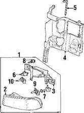
2011 Acura RDX Headlamp Components Assembly Parts Diagram
2011 Acura RDX Headlamp Components Assembly Parts Diagram. The front headlamp consists of:
1) Headlamp assembly Left
2) Bolt
3) Nut
4) Hid bulb
5) High beam bulb
6) Park lamp bulb
7) Signal lamp bulb
8) Parking lamp
9) Signal lamp 10) Cover boot
11) Igniter
12) Seal
13) Cover shield
14) Control module
15) Gasket
16) Repair Kit Upper Inner
17) Repair Kit Upper Outer
18) Repair Kit Lower mazda 6 headlight assembly diagram,kia spectra 2003 inside the headlight diagram,Hyundai sonata headlight assembly diagram,rdx headlamp assembly,diagram of 2010 mazda 3 headlight,
ReadMore..
1) Headlamp assembly Left
2) Bolt
3) Nut
4) Hid bulb
5) High beam bulb
6) Park lamp bulb
7) Signal lamp bulb
8) Parking lamp
9) Signal lamp 10) Cover boot
11) Igniter
12) Seal
13) Cover shield
14) Control module
15) Gasket
16) Repair Kit Upper Inner
17) Repair Kit Upper Outer
18) Repair Kit Lower mazda 6 headlight assembly diagram,kia spectra 2003 inside the headlight diagram,Hyundai sonata headlight assembly diagram,rdx headlamp assembly,diagram of 2010 mazda 3 headlight,
2005 Acura TSX Front Suspension Strut Assembly Parts Schematic Diagram
The following schematic shows the 2005 Acura TSX Front Suspension Strut Assembly Parts Diagram.
1. Strut Assembly
2. Strut
3. Bumper
4. Plate
5. Boot
6. Boot Mount
7. Dust cover
8. Plate
9. Spring
10. Upper seat
11. Mount bushing
12. Mount base
13. Collar
14. Washer
15. Top nut
strut assembly diagram,honda accord suspension diagram,JETTA 4 FRONT STRUT DIAGRAM,cadillac cts 2006 strut mount,diagram of strut assembly,
ReadMore..
1. Strut Assembly
2. Strut
3. Bumper
4. Plate
5. Boot
6. Boot Mount
7. Dust cover
8. Plate
9. Spring
10. Upper seat
11. Mount bushing
12. Mount base
13. Collar
14. Washer
15. Top nut
strut assembly diagram,honda accord suspension diagram,JETTA 4 FRONT STRUT DIAGRAM,cadillac cts 2006 strut mount,diagram of strut assembly,
2002 Acura RSX Piston and Connecting Rod Parts Schematic Diagram
Here is a typical schematic of the 2002 Acura RSX Piston and Connecting Rod Parts and Components Assembly.
A. Piston Rings
B. Piston Pin
C. Engine Block
D. Connecting Rod Bearing Cap
E. Connecting Rod Bolt
F. Connecting Rod Bearings
G. Connecting Rod
H. Piston
2005 hyundai santa fe engine diagram,2005 nissan altima rod bearing,eagle connecting rods assembly,spendal 2002 hyundia connects to,2002 acura mdx engine diagram,
ReadMore..
A. Piston Rings
B. Piston Pin
C. Engine Block
D. Connecting Rod Bearing Cap
E. Connecting Rod Bolt
F. Connecting Rod Bearings
G. Connecting Rod
H. Piston
2005 hyundai santa fe engine diagram,2005 nissan altima rod bearing,eagle connecting rods assembly,spendal 2002 hyundia connects to,2002 acura mdx engine diagram,
2010 Acura MDX Exhaust System Parts and Components Assembly
Below schematic illustrates the 2010 Acura MDX Exhaust System Parts and Components Assembly. The Acura MDX exhaust manifold is made of cast iron which delivers extremely hot exhaust gases with a temperature of up to 1400 degrees Fahrenheit from the cylinder head to the exhaust piping.
1. Converter Right
2. Converter Left
3. Stud Back
4. Gasket Back
5. Outer Right
6. Outer Left
7. Inner Right
8. Inner Left
9. Stay bracket
10. Front pipe
11. Gasket
12. Second converter
13. Gasket
14. Muffler & pipe Right
15. Gasket
16. Muffler Left
17. Gasket
18. Mount ring
19. Second converter, Lower
20. Second converter, Upper
21. Front muffler
22. Rear muffler Right
23. Rear muffler Left
exhaust diagram 1998 camry,2009 nissan maxima exhaust line diagram,suzuki grand vitara 2007 exhaust heat shield parts,2006 cadillac sts heat shield exhaust,2008 ford escape exhaust system parts diagram,
ReadMore..
1. Converter Right
2. Converter Left
3. Stud Back
4. Gasket Back
5. Outer Right
6. Outer Left
7. Inner Right
8. Inner Left
9. Stay bracket
10. Front pipe
11. Gasket
12. Second converter
13. Gasket
14. Muffler & pipe Right
15. Gasket
16. Muffler Left
17. Gasket
18. Mount ring
19. Second converter, Lower
20. Second converter, Upper
21. Front muffler
22. Rear muffler Right
23. Rear muffler Left
exhaust diagram 1998 camry,2009 nissan maxima exhaust line diagram,suzuki grand vitara 2007 exhaust heat shield parts,2006 cadillac sts heat shield exhaust,2008 ford escape exhaust system parts diagram,
Subscribe to:
Posts (Atom)


